WLAN Physical layer | 802.11 Physical layer | WiFi PHY
This article on WLAN Physical layer describes wifi physical layer as per IEEE 802.11 WLAN PHY. The wlan physical layer transmitter and receiver block diagrams are described.
In order to explain physical layer, we will go through wlan frame structure, OFDM symbol structure, wlan modulation code rate table, wlan transmitter and receiver modules and their functions.
Introduction to 802.11
This section describes 802.11 physical layer as defined in IEEE 802.11a-1999 standard. 802.11a operates at 2.4GHz RF frequency and supports data rate up to 54Mbps. There are other popular standards in the 802.11 family 802.11b, 802.11g and 802.11n. 802.11b operates at 2.4GHz and supports data rate up to 11 Mbps, where in DSSS and CCK modulation schemes are employed. 802.11g operates at 5GHz and supports both 11a and 11b standards.
WLAN 802.11 Frame structure
WLAN frame structure consists mainly PLCP Preamble, Signal (Header) part and Data Part. PLCP preamble field, composed of 10 repetitions of a "short training sequence " and two repetitions of a "long training sequence" preceded by a guard interval (GI). Header part consists of 24 bits which is always BPSK modulated. Header part contains Rate (modulation-code rate) and length (Unit of OFDM symbols) of the Data part. Refer page on 11a frame structure for the depictive view of parts of WLAN frame as per 802.11 standard.
In WLAN, one symbol consists of 64 point FFT. It consists of 48 data carriers,
4 pilot carriers, 1 DC and rest of the carriers are used as guard carriers.
The 11a standard defines modulation-code rate table as mentioned below, based on data rate
various physical layer configuration is made.

The Table-1 above mentions different data rates supported by WLAN (i.e. wifi) standard.

The table-2 above mentions parameters of 802.11 WLAN OFDM symbol.
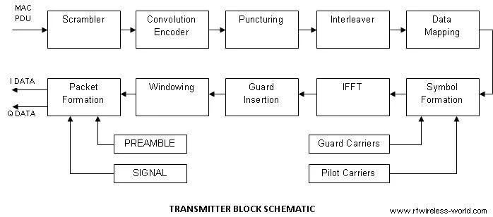
The Transmitter encoding process of 802.11 physical layer is
described in the block schematic below.
For Example, If 18 Mbps data rate is selected, modulation is set to QPSK, coding rate is set to 3/4, coded bits
per carrier is set to 2, coded bits per OFDM symbol is set to 96.
For this case Data bits per OFDM symbol will be 72.
WLAN Physical layer as per 802.11 standard
Let us understand wlan physical layer block diagram as shown in the figure with following sub-sections.
• WLAN Preamble generation and data generation
• WLAN header generation
• WLAN packet formation
WLAN Preamble and Data Generation
Preamble Generation:
Preamble part consists of short training field(STF) and long training field(LTF).
Header Generation:
-Generating the SIGNAL field bits
-Coding and interleaving the SIGNAL field bits
-Mapping the SIGNAL field into frequency domain
-Pilot and Guard insertion
-Transforming into time domain
Data Generation:
The message to be transmitted if it is not already in bits then the same is converted first to ASCII; then it is pre-pended with an appropriate MAC header and a CRC32 is added. Once this is done number of OFDM symbols need to be derived based on length and modulation-code rate. This is used for generating OFDM symbols for the DATA as mentioned below for each symbol.
-represent data which is in octects into bits
-Pre pending the SERVICE field and adding the pad bits, thus forming the DATA
-Scrambling and zeroing the tail bits
-Encoding the DATA with a convolution encoder and puncturing
-Mapping into complex 16-QAM symbols
-Pilot and Guard insertion
-Transforming from frequency to time and adding a cyclic prefix
WLAN packet formation as per 802.11 wifi standard
Packet Formation:
Combine these symbols in the order which includes preamble, Header and data symbols, hence the packet is formed to be transmitted.
The entire process for a message of 100 octets and data rate of 36 Mbit/s is described in the Standard IEEE 892.11a-1999 Annex G.
The receiver consists of all the blocks reverse of the
transmitter except it will have front end synchronization modules for
time offset, frequency offset and channel impairment correction.
This is shown in the figure below. This is achieved using preamble pattern.
After this is done header is decoded as the modulation-code rate is known i.e.
BPSK 1/2. Based on header information viz. rate and length data is decoded
and passed on to the MAC layer for further processing.

WLAN PHY layer RELATED LINKS
WLAN tutorial About wlan 802.11 standards 11a WLAN PHY 11b PHY 11n PHY WLAN 802.11ac WLAN 802.11ad 11a vs 11b vs 11g vs 11n WLAN routers WLAN providers WLAN DCF vs PCF Adhoc vs Infrastructure WLAN 802.11 channels WLAN Frame Structure IR vs SS vs RF WLAN Terminology WLAN vs WiMAX
11ac, 11ad, 11af, 11n, 11ax wlan tutorial Links
WLAN 802.11ac tutorial
WLAN 802.11ad tutorial
WLAN 802.11af tutorial
WLAN 802.11ax tutorial
WLAN 802.11n Physical layer
WLAN MAC frames Links
WLAN Association Request and response frame
WLAN authentication Request and deauthentication frame
WLAN beacon frame
WLAN passive vs active scanning frame
WLAN Probe Request and response frame
WLAN reassociation Request and response frame
WLAN RTS and CTS frame
Other Standard Physical Layers
• Wireless physical layer overview
• 11b physical layer
• 11a physical layer
• fixed wimax physical layer-OFDM
• mobile wimax physical layer-OFDMA
• 11n physical layer
• GSM Physical layer
• TD-SCDMA Physical layer
• GPRS physical layer
• LDACS1 Physical layer
• 10,40,100 Gigabit Ethernet Physical layer
• Zigbee Physical layer
• WCDMA Physical layer
• Bluetooth Physical layer
• WLAN 802.11ac Physical layer
• WLAN 802.11ad Physical layer
• LTE Physical layer