WLAN 802.11ad physical layer
This page of WLAN 802.11ad tutorial covers WLAN 802.11ad physical layer. It covers different 802.11ad physical layer configurations such as control PHY, single carrier PHY, OFDM PHY and low power single carrier PHY.
All the physical layer versions have different contents in their respective packet structures.
All the packet structures contain preamble, header and payload and TRN fields in common.
Preamble comprised of STF(Short Training Field) and CEF(Channel Estimation Field).
It helps in AGC and frequency offset synchronization.
It also helps in differentiating type of PHY used.
The receiver utilizes CE field for channel estimation and correction.
Preamble is constructed using Golay Sequences. Each sequence consists of bipolar symbols(+1 or -1).
These different preamble types carry basic building blocks as golay sequences e.g.
Ga128 and Gb128.
Preamble is followed by header field. This header contents are different for OFDM, SC and control PHY.
Header carry MCS, length of data payload or a checksum.
They carry many informations, most important among them is
MCS(Modulation-coding scheme). This MCS convey information of modulation and coding scheme used for the payload .
This will help receiver decode the payload carried in the respective packet/frame.
For more information on header refer WLAN-11ad tutorial.
TRN information is optional and it includes beamforming related information.

Figure-1 mentions OFDM PHY packet structure, as shown in the figure, header is always QPSK modulated. As the modulation-code rate of header is known at the receiver, it is decoded first after front end synchronization is performed on the received packet using known preamble sequence and received one. Based on the decoded MCS from header, 802.11ad physical layer receiver modules for OFDM variant is tuned and payload is decoded consecutively. Refer physical layer transmitter modules and receiver modules as described below.
WLAN 802.11ad OFDM Physical Layer Transmitter

Fig:1 OFDM-802.11ad PHY Tx
Scrambler:
The binary information from MAC layer is passed to the scrambler with following polynomial.
This module removes long string of ones and zeros if present in the input data.
This will help meet adjacent channel rejection specification of the 11ad compliant device.
This will help more transitions from 1 to 0 and 0 to 1 and
hence will easy in time synchronization at the receiver.
Scrambler polynomial: X7+X4+1
Scrambler is used at the transmit side and descrambler is used at the receiver side.
Refer scrambler and descrambler circuit with matlab code.
LDPC Encoder:
LDPC stands for Low-Density Parity Check. It is forward error correction coding technique.
This coding technique is common to the different PHY versions e.g. Control PHY, SC PHY and OFDM PHY.
It is based on a common codeword length of 672 bits each carrying either 336, 504, 420 or 546 payload bits to
achieve different code rates 1/2, 3/4, 5/8 or 13/16 respectively. The same has been mentioned in the following table-1.
| LDPC Code Rate | Code Word Size | Number of Data Bits |
|---|---|---|
| 1/2 | 672 | 336 |
| 5/8 | 672 | 420 |
| 3/4 | 672 | 504 |
| 13/16 | 672 | 546 |
3X repetition:
This repetition is applied to 802.11ad header part. The same header data information is available three times in the 802.11ad frame. This helps in error correction at the receiver. This is required as header is the most critical information in the frame which need to be protected in the harse channel environments.
Carrier Mapping/Modulation:
This module converts bits into complex symbols. Various modulation schemes such as SQPSK, QPSK, 16-QAM and 64-QAM are used based on MCS.

Symbol Formation:
This module takes care of OFDM symbol formation.
The 802.11ad physical layer version OFDM uses 16 pilot subcarriers, 1 DC carrier, 336 data subcarriers and
159 guard subcarriers.
This is formed as per IFFT structure shown in the figure.
IFFT:
The 512-point IFFT is performed. IFFT converts frequency domain data symbols to time domain data symbols.
Refer 16 point IFFT implementation in MATLAB for more.
Cyclic Prefix Insertion:
This is referred as guard interval insertion.
In this last few samples of OFDM symbol are inserted at the beginning.
About 25% of overhead is used in 11ad OFDM physical layer.
This is equal of 1/4 of the one symbol samples.
In other words, 11as uses cyclic prefix of value equal to 1/4.
Packet Formation:
In this modules 11ad packet is constructed as shown in the 11ad OFDM packet structure shown previously.
802.11ad OFDM packet consists of preamble, header and payload.
Windowing:
The windowing function will smoothen the transition between adjacent fields in the packet structure.
This is not applied to SC modulated packet fields as well as to preamble part.
Following is one of the transfer function used for windowing function.
WT (t) = sin2 ( π/2(1/2+t/TR)) ..For -TR/2 < t <= TR/2
= 1 .. For -TR/2 < t <= T - TR/2
= sin2 ( π/2(1/2- ((t-T)/TR))).. For T-TR/2 < t <= T + TR/2
RF Upconversion:
Necessary RF up conversion is performed. Up conversion converts baseband data to RF modulated data to be
transmitted over the air. Various RF frequencies are supported. It includes 2.4 GHz, 5 GHz and 60 GHz.
WLAN 802.11ad OFDM Physical Layer Receiver

Fig:2 OFDM-11ad PHY Rx
• First Down conversion and de-windowing is applied to the received packet at
the 11ad OFDM PHY receiver. Next front end synchronization is performed as described in the next
few steps before demodulation and decoding is carried out.
• Start of the frame is detected by way of threshold detection.
Basically algorithm should be implemented which differentiates between noise and actual WLAN 11ad packet.
This is also referred as coarse time offset estimation and correction.
Now Cyclic prefix removal is performed.
• Next fine time offset estimation and correction is performed
to the level of 1 sample resolution.
• Next frequency offset estimation and correction is performed.
• After FFT is performed,complex channel response coefficients are found using
channel estimation method in the frequency domain using preamble sequences
(Either STF or CEF or both).
• Now Channel equalization is performed using estimated channel response coefficients for each of the
symbols of the OFDM packet.
• After channel equalization using channel response, phase rotation is performed using estimated
phase rotation using pilot subcarriers embedded in the OFDM symbol.
This is basically referred as phase de-rotation.
• Symbol deformation is performed which removes pilots, DC and guard subcarriers from each
of the OFDM symbols.
• Demapping is performed on the data subcarriers as required based on MCS.
It can be QPSK, 16QAM or 64QAM.
• After demapping, LDPC decoding is done. For header first de-repetition(3X)
is performed before LDPC decoding is carried out.
• Finally descrambling is applied to retrieve the MAC data.
WLAN 802.11ad Control Physical Layer Transmitter

Fig:3 Control 802.11ad PHY Tx
Control PHY Preamble: consists of STF and CEF as per following fields.
STF = { 48 times Gb128, once -Gb128, once -Ga128 }
= 50 *128=6400 Tc in length
CEF = { Gu512, Gv512, -Gb128 }
= 9 *128 = 1152 Tc in length
Where in,
Gu512={-Gb128,-Ga128,+Gb128,-Ga128}
Gv512={-Gb128,+Ga128,-Gb128,-Ga128}
Control PHY Header:Consists of total 40 bits length.
Control packet header =
{Reserved-1 bit,
Scrambler initialization-4 bits
Length of data field-10 bits
Packet type-1 bit, mentions beamforming training field is for transmitter or receiver
Training length-5 bits, specifies beamforming training field is used or not and what is the length.
Turnaround-1bit,
Reserved-2 bits,
HCS-16 bits
}
Scrambler:
It is same as described above in the OFDM physical(PHY) layer.
LDPC Encoder:
It is same as described above in the OFDM PHY. It uses Shortened 3/4 LDPC is used resulting into 1/2 or less code rates.
It uses 672 its of codeword length.
Differential Encoder:
Refer differential encoder vs decoder for more.
Modulation:
It is using π/2 BPSK modulation technique.
π/2 shift is being used compare to normal BPSK modulation in order to avoid zero crossing in the I/Q diagram.
Only MCS0 is supported in this PHY version.
32x Spreading:
This module does 32 times spreading with Ga32 and π/2 rotation.
Spectrum Shaping:
Not defined in the standard.
Up conversion:
As described above, refer basics of RF upconversion for more.

Packet formation:
This is as per the 802.11ad control frame structure as shown above.
RF Upconversion:
Same as mentioned in OFDM 802.11ad PHY above.
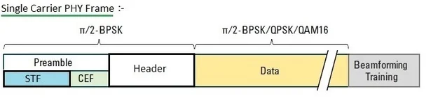
WLAN 802.11ad Single Carrier Physical Layer Transmitter
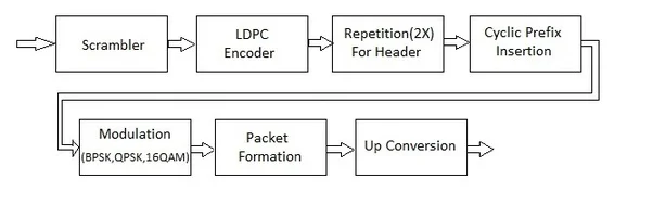
Fig:4 SC PHY Tx
This 11ad physical layer mode takes care of data rates ranging from 385 Mbps to 4.620 Mbps which depends on MCS. The basic packet structure is same in SC and low power SC PHY versions, but 16QAM is not employed in low power SC mode to save the energy usage.
The SC PHY layer transmitter consists of scrambler, LDPC Encoder, repetition block(2X), CP insertion, modulation before packet is formed as
per structure mentioned below. No spectrum shaping is defined. After baseband processing I/Q packet is modulated using RF carrier and
transmitted over the air.
About 12 modulation-coding schemes from MCS1 to MCS12 are supported.
This single carrier modulation schemes include BPSK, QPSK or 16QAM modulations.
These use RF carrier at the channel center frequency and with symbol rate of about 1.76 Gsymbol per second.
SC PHY preamble: Preamble is composed of STF and CEF with following details:
STF = { 16 times Ga128 , -Ga128 }
CEF = { Gu512, Gv512, -Gb128 }
Gu512 and Gv512 is same as mentioned above.
SC PHY header: SC header field is 64 bit in length with following details:
SC header= {
{7 bits(scrambler init.),
5 bits(MCS),
18 bits(data Length),
1 bit(add.PPDU),
1 bit(packet type),
5 bits(training length),
1 bit(aggregation),
1 bit(beam tracking request),
4 bits(last RSSI),
1 bit(turnaround),
4 bits(reserved),
16 bits(HCS)
}
WLAN 802.11ad Low Power Single Carrier Physical Layer Transmitter

Fig:5 Low Power SC 802.11ad PHY Tx
This Low Power SC physical layer transmitter consists of Scrambler, RS Encoder(224,208), Block Encoder, Block interleaver, CP insertion, modulation types(π/2 -BPSK, π/2 -QPSK). Refer RS Encoder matlab code as per WiMAX OFDM PHY layer specifications.

Packet Formation:
After the modulation packet is formed as per packet structure shown above.
After which necessary up conversion is carried out based on RF frequency required.
Similar posts on 802.11ad WLAN
802.11ad tutorial 11ad PHY Layer 11ad conformance tests 11ac conformance 11n vs 11ac vs 11ad
RELATED LINKS
What is wlan?
WLAN standards-11a,11b,11g,11n,11ac
11a WLAN Physical layer
11b WLAN Physical layer
11n WLAN Physical layer
WLAN 802.11-ac
WLAN 802.11-ad
Difference between 11a,11b,11g,11n
Difference between 11-n,11-ac and 11-ad
WLAN router providers
WLAN providers
Front end synchronization related links
Time offset estimation and correction basics
Frequency offset estimation and correction basics
channel estimation and equalization with matlab code
Frequency offset estimation and correction with matlab code
Time offset estimation and correction matlab code
Other Standard Physical Layers
• Wireless physical layer overview
• 11b physical layer
• 11a physical layer
• fixed wimax physical layer-OFDM
• mobile wimax physical layer-OFDMA
• 11n physical layer
• GSM Physical layer
• TD-SCDMA Physical layer
• GPRS physical layer
• LDACS1 Physical layer
• 10,40,100 Gigabit Ethernet Physical layer
• Zigbee Physical layer
• WCDMA Physical layer
• Bluetooth Physical layer
• WLAN 802.11ac Physical layer
• LTE Physical layer