OFDMA Physical layer basics
Introduction
This article describes OFDMA basics, OFDMA frame structure,OFDMA symbol,OFDMA Physical layer as per IEEE 802.16e mobile wimax standard.It also explains OFDMA TDD frame which consists of PUSC, FUSC and AMC Zones in the downlink and PUSC/AMC zones in the Uplink. We will go through Mobile WiMAX OFDMA physical layer which consists of scrambler, convolution coding,Interleaving,repetition coding,modulation,subchannel formation, OFDMA data mapping,subframe formation,IFFT and Guard insertion.
We will see physical layer with the example of 1024 FFT for Downlink chain which is used by Base Station to send information to Mobile subscribers. This is also called as mobile wimax physcial layer.
OFDMA Basics
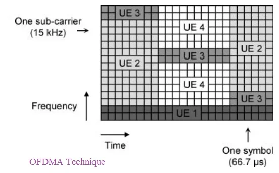
OFDMA stands for Orthogonal Frequency Division Multiple Access. It is considered as a modulation and multiple access technique for next generation wireless networks for such as Mobile WiMAX and LTE. OFDMA is an extension of Orthogonal Frequency Division Multiplexing (OFDM), which is currently the modulation of choice for high speed data access systems such as IEEE 802.11a/g wireless LAN (WiFi) and IEEE 802.16a/d/e wireless broadband access systems (WiMAX) In current OFDM systems, only a single user can transmit on all of the subcarriers at any given time, and time division or frequency division multiple access is employed to support multiple users. OFDMA, on the other hand, allows multiple users to transmit simultaneously on the different subcarriers per OFDM symbol. Hence it is often referred as Multiuser-OFDM.
Mobile WiMAX
IEEE 802.16e-2009 defines OFDMA Physical layer and MAC layer, popularly known as Mobile WiMAX. Mobile WiMAX is used for broadband data communication similar to cellular technologies. Base Station and Subscriber station equipments available for Mobile WiMAX technology have been developed for different RF frequencies viz. 2.3-2.4GHz, 2.5-2.7GHz, 3.3-3.8GHz as required for different countries spectrum allocations. Commonly used beam widths range from 1.25 MHz to 20 MHz in OFDMA. It supports FFT sizes of 128, 512, 1024 and 2048, but 512 and 1024 are commercialized by most of the equipment vendors and the same is certified by WiMAX Forum. Following diagram explains TDD frame structure of OFDMA.
Frame Structure-TDD
As depicted in the frame structure below, allocations of the resource here is in two dimension i.e. time as well as frequency. X axis represent Time (OFDM Symbols) and Y axis represent Frequency (Sub-channels.) Mobile WiMAX supports PUSC, FUSC and AMC Zones in the Downlink and PUSC and AMC zones in the Uplink as mandatory zones. In the example here we will discuss PUSC zone. As mentioned Downlink Burst 1, 2 in the downlink sub frame part occupy both time as well as frequency resources for data to be transmitted over the air. Similarly Uplink Burst 1 and 2 in the uplink sub frame part also occupy both time as well as frequency resources. For more information on mobile wimax terms visit our page on terminology.
OFDMA Symbol description
As per mobile wimax, 1024 point FFT consists of 30 sub channels and each sub channel is composed of 24 data subcarriers. Hence one symbol of 1024 subcarriers will have 720 data subcarriers. It also has 120 pilot subcarriers,92 left guard and 91 right guard subcarriers, 1 DC subcarrier making total of 1024(equal to 720+120+1+92+91). Remember as PUSC will have 2 symbols in a slot, it will carry 48 data subcarriers in a sub channel for which renumbering sequence has been provided to permute data subcarriers in a sub channel across 1 slot (i.e. 2 symbols).
Mobile WiMAX Physical Layer as per OFDMA Specifications
There are many software applications available which is known as vector signal generators from R&S, Agilent, Anritsu to generate 16e compliant Base band signal for Base Station. Most common inputs for generating IQ are BW, Cyclic prefix, FFT size, DL_IDcell or DL_Perm_Base (0 to 31), Sector (0,1,2),Frame duration, DL Ratio, Repetition coding for DL MAP, Sub channel Bit map, No. of downlink Bursts and information fields for each downlink bursts. These Information fields for each burst are DIUC, OFDMA Symbol offset, Sub-channel offset; boosting, Number of OFDMA Symbols, Number of Sub-channels and Repetition coding factor (0, 2, 4, and 6). Sometimes preamble sequence number (range 0 to 113) is given in place of IDcell and sector as input to generate baseband IQ signal.

As mentioned in the Block diagram MAC data will go through following modules.
1. Scrambler-
It is combination of LFSR (Linear Feedback Shift Registers )and Ex-OR gates. It will make data randomize and removes long string of 0s and 1s. Hence reduce the PAPR which is considered to be major problem of OFDMA based Physical layer. Structure follows Pseudo Random Binary Sequence (PRBS) generator with polynomial 1+ X14+ X15.
2. Convolution coding and Puncturing-
Before feeding the MAC data to PHY modules FEC size is
calculated based on data to be carried over the burst based on slot
concatenation rule mentioned in the standard and mod-code rate table.
Each FEC block is encoded by the binary convolution encoder,
which shall have native rate of 1/2, a constraint length equal to 7.
Puncturing module removes the bits from the output of the convolution encoder, hence bit rate will increase.
3. Interleaving-
There are two permutation equations performed in this block. These equations depend on ncpc and ncbps. Ncpc is no. of coded bits per subcarrier, i.e., 2, 4, or 6 for QPSK, 16-QAM or 64-QAM, respectively. Ncbps is no. of coded bits per slot, Ncbps= (No. Of uncoded bits per FEC block*(1/Rate)).Example: For QPSK ½, Repetition Factor=1 (no repetition), 2 sub channels and 2 no. Of OFDMA symbols used. It has one FEC block with 12 Un-coded bytes and 24 coded byes.
4. Repetition coding-
Repetition coding can be used to further increase signal margin over the modulation and FEC mechanisms. For the downlink, the number of the allocated slots (Ns) shall be in the range of, R*K to R*K + (R-1) where K is the number of the required slots before applying the repetition scheme. For example, when the required number of slots before the repetition is 10 (Equal K) and the repetition of R Equal to 6 shall be applied for the burst transmission, than the number of the allocated slots (Ns) for the burst can be from 60 slots to 65 slots.
5. Digital Modulation-
After interleaving and appropriate repetition coding is chosen, the data bits are entered serially to the constellation mapper. Gray mapped QPSK and 16-QAM shall be supported, whereas the support of 64-QAM is optional. The constellations shall be normalized by multiplying the constellation point with the factor c to achieve equal average power as described in Equation below:
(I + j*Q( ×c, where c is the normalization factor.
6. Sub channel Formation-
For DL Partially Used Sub channelization (PUSC) and all UL modes, the set of used subcarriers, that is, data and pilots, is first partitioned into sub channels, and then the pilot sub carriers are allocated from within each sub channel. In PUSC, each sub channel contains its own set of pilot subcarriers.
Follow steps mentioned below.
1. Dividing the total subcarriers into the number of clusters (Nclusters) containing 14 adjacent subcarriers each (starting from carrier 0). The number of clusters, Nclusters, varies with FFT sizes.
These are called Physical clusters.
2. Renumber the physical clusters into logical clusters using the following formula:
RenumberingSequence PhysicalCluster First DL zone, or Use All SC indicator = 0 in STC_DL_Zone_IE
RenumberingSequence PhysicalCluster + 13* DL_PermBase mod Nclusters, otherwise
NOTE: Renumbering sequence has been provided in symbol table.
3. Allocate logical clusters to groups. The allocation algorithm varies with FFT sizes.
For 1024 FFT size, dividing the clusters into six major groups.
Group 0 includes 12 clusters 0-11, group 1 includes 8 clusters 12-19, group 2 includes 12 clusters 20-31, group 3 includes 8 clusters 32-39, group 4 includes 12 clusters 40-51, group 5 includes 8 clusters 52-59.
Note that these groups may be allocated to segments.
By default group 0 is allocated to sector 0.
Group 2 is allocated to sector 1. Group 4 to is allocated sector 2
4. Allocating subcarriers to sub channel in each major group is performed separately
for each OFDMA symbol by first allocating the pilot carriers within each cluster,
and then taking all remaining data carriers within the symbol. The parameters vary with FFT sizes.
For 1024 FFT size, Use the parameters from Symbol Table, with
basic permutation sequence 6 for even numbered major groups(G0,G2,G4), a
nd basic permutation sequence 4 for odd numbered major groups(G1,G3,G5),
to partition the subcarriers into sub channels containing 24 data subcarriers in each symbol.
7. OFDMA data mapping
A slot in the OFDMA PHY requires both a time and sub channel dimension for completeness and is the minimum possible data allocation unit.
The definition of an OFDMA slot depends on the OFDMA symbol structure, which varies for uplink and downlink and it depends on zone type.
Data outputted from modulator block is broken into size (1 slot equal to No. of sub channel by No. of OFDMA symbols, depends on DL FUSC , DL PUSC or UL PUSC .(Somewhat similar to FTDMA)
DL PUSC Slot structure: 1 sub-channel by 2 OFDMA symbol
OFDMA Data Mapping in downlink should be done as per following steps.
1) Segment the data after the modulation block into blocks sized to fit into one OFDMA slot.
2) Each slot shall span one sub channel in the sub channel axis and one or more OFDMA symbols in the time axis, as per the slot definition in 8.4.3.1 (see Figure 15 for an example). Map the slots such that the lowest numbered slot occupies the lowest numbered sub channel in the lowest numbered OFDMA symbol.
3) Continue the mapping such that the OFDMA sub channel index is increased. When the edge of the Data Region is reached, continue the mapping from the lowest numbered OFDMA sub channel in the next available symbol.
8. DL sub frame formation-
DL Sub frame composed of Preamble, FCH, Maps (DLMAP, ULMAP) and one or more number of Downlink bursts. These fields are formed and mapped as per the TDD frame structure outlined above based on FFT size and other useful parameters.
9. IFFT-
There are IFFT sizes 2048, 1024, 512 and 128 mentioned in the standard but only 512 and 1024 have been adopted by most of the vendors as per WiMAX forum published specifications.
10. Guard insertion-
One of the main advantages of OFDM is its effectiveness against the multi-path delay spread frequently encountered in mobile communication channels. The reduction of the symbol rate by N times, results in a proportional reduction of the relative multi-path delay spread, relative to the symbol time. To completely eliminate even the very small ISI that results, a guard time shall be introduced for each OFDM symbol. The guard time must be chosen to be larger than the expected delay spread, such that multi-path components from one symbol cannot interfere with the next symbol. The value of CP i.e. Tg can be T/4, T/8, T/16, T/32.
Pl. note all the figures are taken from IEEE standard and wimax forum released documents to demonstrate the concept of OFDMA Physical layer.
References
1. EEE standard 802.16-2004 OFDMA
2. IEEE standard 802.16e-2005 OFDMA
3. wimax_forum_mobile_system_profile_v1_40
Other Standard Physical Layers
• Wireless physical layer overview
• 11b physical layer
• 11a physical layer
• fixed wimax physical layer-OFDM
• mobile wimax physical layer-OFDMA
• 11n physical layer
• GSM Physical layer
• TD-SCDMA Physical layer
• GPRS physical layer
• LDACS1 Physical layer
• 10,40,100 Gigabit Ethernet Physical layer
• Zigbee Physical layer
• WCDMA Physical layer
• Bluetooth Physical layer
• WLAN 802.11ac Physical layer
• WLAN 802.11ad Physical layer
• LTE Physical layer