LoRa wireless tutorial | LoRa tutorial | RF Wireless World
This page of RF Wireless World covers LoRa wireless system tutorial with features. The LoRa tutorial covers LoRa RF bands, LoRa PHY, LoRa MAC frame structure, LoRa Protocol layers, LoRa device classes etc.
LoRa technology is used as wide area network wireless technology. There are different frequency bands defined in US (902 to 928 MHz), EU (863 to 870 MHz) , China (779 to 787 MHz) and other regions to be used in LoRa wireless technology based network. It is low power, long range and low data rate based technology developed with initiative by Samtech.
LoRa network consists of gateways, network servers and end devices. The network topology is star of stars. End devices are also known as motes and gateways are known as base stations or concentrators in LoRa network system.
End devices and Gateways are connected wirelessly using ISM bands specified with single hop. Gateways and network servers are connected using IP backhaul connections.
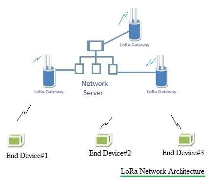
The figure-1 depicts LoRa network architecture. Customer information database is housed in servers. Communication between end devices and gateways are carried at different channels and different data rates. LoRa supports adaptive data rate from 0.3 Kbps to 50 Kbps.
LoRa Frame Structure

The transmission from end device to gateway is referred as "uplink" and transmission from gateway to end device is referred as "downlink". There are different classes supported in LoRaWAN network viz Class A, Class B and Class C.
As shown in figure LoRa frame consists of uplink part and downlink part. In Class-A, LoRa frame has one uplink slot followed by two downlink slots. The frame is as per TDD topology. Refer LoRaWAN classes for other LoRa classes.
LoRa Protocol Stack
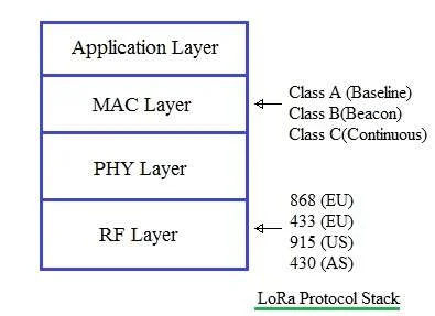
The figure-2 depicts LoRa protocol stack consisting of Application layer, MAC layer, PHY layer and RF layer.
• Data from application layer and MAC commands required to establish connection between End device and gateway
are carried as MAC payload.
• MAC layer constructs the MAC frame using MAC payload.
• PHY layer uses MAC frame as PHY payload and constructs the PHY frame after inserting Preamble, PHY header, PHY header CRC and entire frame CRC.
• RF layer modulates the PHY frame on required ISM RF carrier as per regulatory requirement and transmits on to the air.
Note: Information provided on this page is derived from LoRaWAN Specification V1.0 released on Jan.2015 by LoRa™ Alliance. LoRa alliance is responsible for changes to the specifications at any time without notice. RF Wireless World is not responsible for any issues with regard to the same. Refer latest specifications published by LoRa Alliance ( https://www.lora-alliance.org ) for any changes required to be done for the products under development as per LoRa standard.
Similar posts on LoRa Wireless technology
Main page LoRa tutorial LoRa Frequency Bands LoRa protocol stack LoRa MAC layer LoRaWAN classes LoRa features LoRa Transceiver module