Understanding 5G NR Physical layer | 5G PHY layer overview
This 5G NR physical layer provides overview of PHY layer modules as per 5G New radio 3GPP standard. It describes processing of PDSCH and PUSCH channels through 5G physical layer.
Introduction:
The 5th generation wireless access tachnology is known as NR (New Radio). It follows 3GPP series of standards similar to GSM, CDMA and LTE.
3GPP organization has been developing specifications for 5G NR since few years. First specifications have been published in Dec. 2017
which suppors NSA (Non Standalone) where in 5G compliant UE relies on existing LTE for initial access and mobility.
In June 2018, SA versions of 5G NR spefications have been finalized which works independent of LTE.
There are three different use cases of 5G NR technology viz. eMBB (Enhanced Mobile Broadband),
mMTC (Massive machine type communications) and URLLC (Ultra Reliable Low Latency Communication).
The 5G PHY layer is specified in 3GPP TS 38.200 series of documents.
There are two main components in 5G NR network viz. UE (i.e. mobile subscriber) and gNB (i.e. base station). gNBs are connected with 5G Core in the backend. The connection from gNB to UE is known as downlink which uses PBCH, PDSCH and PDCCH channels for carrying different data/control informations. The connection from UE to gNB is known as uplink which uses PRACH, PUSCH and PUCCH channels. Refer 5G NR network Architecture >>.
5G NR Numerology
5G NR Supports two frequency ranges FR1 (Sub 6GHz) and FR2 (millimeter wave range, 24.25 to 52.6 GHz). NR uses flexible subcarrier spacing derived from basic 15 KHz subcarrier spacing used in LTE. Accordingly CP length is choosen. This is shown in the table-1. Refer Physical layer timing unit >>.
| μ | Δf = 2μ.15 | Cyclic Prefix |
|---|---|---|
| 0 | 15 KHz | Normal |
| 1 | 30 KHz | Normal |
| 2 | 60 KHz | Normal, Extended |
| 3 | 120 KHz | Normal |
| 4 | 240 KHz | Normal |
| 5 | 480 KHz | Normal |
Table-1: μ, Subcarrier spacing, CP, PRBs
Both frequency ranges FR1 and FR2 use different 5G numerology as mentioned in the table-2. Subcarrier Spacing of 15/30 KHz is supported for below 6 GHz 5G NR where as 60/120/240 KHz is supported for mmwave bands. Maximum bandwidth of 100 MHz is supported in sub-6 GHz where as 400 MHz is supported in mmwave frequency ranges. In LTE, maximum BW of 20 MHz was used.
| Parameters | Sub-6 GHz range | mmWave range |
|---|---|---|
| Carrier aggregation | upto 16 carriers | |
| BW per carrier | 5/10/15/20/25/40/50/60/80/100 MHz | 50/100/200/400 MHz |
| Subcarrier spacing | 15/30/60 KHz | 60/120/240 KHz |
| Modulation Scheme | DL/UL: 256 QAM | |
| MIMO | DL: upto 8 layers, UL: upto 4 layers |
DL: upto 2 layers, UL: upto 2 layers |
| Duplex mode | TDD (focus), FDD | TDD |
| Access scheme | DL: CP-OFDM, UL:CP-OFDM, DFT spread OFDM | |
Table-2: 5G NR Sub-6 GHz and mmwave parameters as per 3GPP Rel.15
| Subcarrier spacing (KHz) | 15 | 30 | 60 | 120 | 240 |
| Symbol duration (µs) | 66.7 | 33.3 | 16.7 | 8.33 | 4.17 |
| CP duration (µS) | 4.7 | 2.3 | 1.2 (Normal CP), 4.13 (Extended CP) | 0.59 | 0.29 |
| Max. nominal system BW (MHz) | 50 | 100 | 100 (sub-6 GHz), 200 (mmwave) | 400 | 400 |
| FFT size (max.) | 4096 | 4096 | 4096 | 4096 | 4096 |
| Symbols per slot | 14 | 14 | 14 (normal CP), 12 (extended CP) | 14 | 14 |
| Slots per subframe | 1 | 2 | 4 | 8 | 16 |
| Slots per frame | 10 | 20 | 40 | 80 | 160 |
Table-3: Subcarrier spacing, Number of OFDM symbols and slots
5G NR Frame Structure

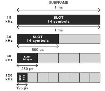
A frame has duration of 10 ms which consists of 10 subframes having 1ms duration each similar to LTE technology. Each subfame can have 2μ slots. Each slot typically consists of 14 OFDM symbols. The radio frame of 10 ms are transmitted continuously as per TDD topology one after the other. Subframe is of fixed duration (i.e. 1ms) where as slot length varies based on subcarrier spacing and number of slots per subframe. As shown below, it is 1 ms for 15 KHz, 500 µs for 30 KHz and so on. Each slot occupies either 14 OFDM symbols or 12 OFDM symbols based on normal CP and extended CP respectively.
5G NR supports Mini Slot concept which helps in achieving very low latency in data transmission. It supports 2, 4 or 7 OFDM symbols.

The figure depicts resource grid of 5G NR with symbols in time axis and subcarriers in frequency axis. 12 subcarriers form one PRB (Physical Resource Block). 5G NR supports 24 to 275 PRBs in a single slot. Occupied BW of 34.56 MHz (minimum) and 396 MHz (maximum) can be achieved for 120 KHz subcarrier spacing. One SS/PBCH Block occupies 4 OFDM Symbols in time domain and 24 PRBs in frequency domain. 5G NR SS consists of PSS and SSS as specified for LTE.
Understanding 5G Physical layer using PDSCH and PUSCH
In 5G NR there are various physical channels in the downlink (from gNB to UE) and uplink (from UE to gNB).
Downlink channels: PDSCH, PDCCH, PBCH
Uplink channels: PRACH, PUSCH, PUCCH
There are specific physical signals present in both downlink and uplink for various
purposes. Front loaded DMRS (Demodulation Reference signal) is used for both PDSCH and PUSCH channels.
We will consider OFDM with CP for both downlink and uplink chain.
Uplink also uses DFT Spread OFDM with CP for improved coverage.
PDSCH channel processing through 5G NR Physical layer

Let us understand PDSCH channel processing using 5G NR physical layer modules.
The PDSCH channel is used to carry DL user data, UE specific upper layer informations (layer-2 and above), system informations and paging.
Let us understand PDSCH channel data (i.e. transport block) processing through 5G NR physical layer modules or blocks.
Transport block size calculation is mentioned in 3GPP TS 38.214(section 5.1.3.2).
One can also refer transport block size calculation at TBS calculation page >>
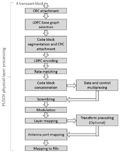
➤As shown in the figure, CRC is added to each of the transport blocks to provide error detection.
➤This is following by LDPC base graph as per transport block size (small or large).
➤Now transport block is segmented into code blocks. CRC is appended to each of these code blocks.
➤Each of the code blocks are individually encoded using LDPC encoder, which are rate matched after encoding process.
➤Code block concatenation is performed to form codewords for transmission over PDSCH channel.
About 2 codewords are transmitted simultaneously on single PDSCH channel.
Single codeword is used for 1 to 4 layers where as 2 codewords are used for 5 to 8 number of layers.
➤All the codewords are scrambled and modulated to generate complex data symbols before layer mapping.
It uses QPSK, 16QAM, 64QAM and 256QAM modulation schemes.
➤The modulated data symbols are mapped to either 4 or 8 layers.
➤The layers are mapped with number of antenna ports reserved for PDSCH use and complex modulated data symbols
are mapped to RBs (Resource Blocks) in the resource grid as per subcarrier spacing.
Antenna ports range is {1000,...,1011}.
DMRS values are inserted during resource element mapping used for channel estimation and
equalization at the UE receiver. OFDM signal is generated after RE (Resource Element) mapping.
➤The downlink PDSCH is received by UE which consists of reverse modules of 5G NR physical layer in order to decode the
transport block back before passing the information to upper layers.
PUSCH channel processing through 5G Physical layer
Let us understand PUSCH channel data (i.e. transport block) processing through 5G physical layer modules or blocks.
PUSCH channel is used for transmission of UL SCH and layer-1 and layer-2 control information.
The procedure for UL transport block in PUSCH processing is same as described above.
It uses additional π/2-BPSK modulation scheme in addition to the one listed above in PDSCH processsing.
It also uses DMRS signals for channel
estimation and equalization process to help in decoding process.
➤In addition to above blocks, the PUSCH processing uses transform precoding after layer mapping operation.
This is optional and UE implementation specific. DFT transform precoding is used for single layer transmissions.
PUSCH supports single codeword which can be mapped maximum upto 4 layers.
➤5G NR UE uses codebook based transmission and non codebook based transmissions.
➤In 5G NR mapping to resource grid is done frequency wise first before time in order to have easier decoding proceess
at the gNB receiver.
5G PHY layer (5G L1) References
5G physical layer (L1) specifications are defined in following 3GPP 5G New Radio (NR) series of
documents.
3GPP TS 38.201 : General description
3GPP TS 38.202 : Services provided by physical layer
3GPP TS 38.211 : Physical channels and modulation
3GPP TS 38.212 : Multiplexing and channel coding
3GPP TS 38.213 : Physical layer procedures for control
3GPP TS 38.214 : Physical layer procedures for data
3GPP TS 38.215 : Physical layer measurements
Refer overview of other 5G layers which include 5G NR MAC layer >>, 5G NR RLC layer >> and various RRC IEs >> to understand 5G protocol stack.
5G NR Numerology | 5G NR Terminology
5G NR Control channels | 5G NR Traffic Channels | 5G NR Reference Signals and sequences
5G TECHNOLOGY RELATED LINKS
5G basic tutorial
5G Frequency Bands
5G millimeter wave tutorial
5G mm wave frame
5G millimeter wave channel sounding
Difference between 4G and 5G
5G testing and test equipments
5G network architecture
Other Standard Physical (PHY) Layers
Following links are resources on wireless PHY layers as per other standards which include LTE PHY, WiMAX PHY, WLAN PHY, Zigbee PHY, Bluetooth PHY and so on.