How to interface PHY and MAC layers
Now-a-days wireless devices are rapidly developing as per IEEE and 3GPP standards. The standards such as WLAN, WiMAX, Zigbee are based on IEEE publications. GSM, LTE, UMTS are based on 3GPP series of standards.
As these standards define PHY and MAC layer specifications separately and hence products based on these standards should house both of these functionalities. This often leads software developers to have knowledge on how to interface PHY and MAC layers. This article covers the physical layer and MAC layer interfacing. This interface guide is very useful for connecting physical layer (i.e. layer-1) and MAC layer (i.e. layer-2) as required in WLAN,WiMAX,LTE and so on.
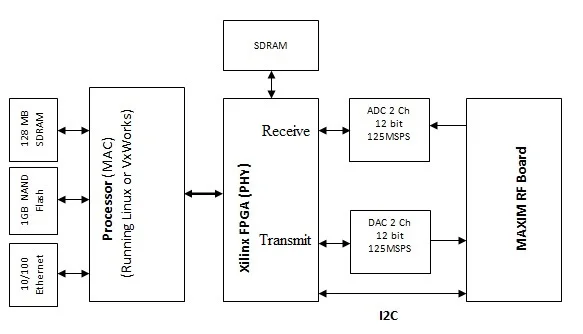 fig-1 PHY,MAC and RF interface diagram
Figure-1 mentions PHY, MAC and RF interface diagram. As shown in the figure, XILINK FPGA is used to port PHY layer and processor is used to port MAC layer. This configuration can be used for implementation of PHY and MAC layer stacks as per WLAN and WiMAX standards. SDRAM is used as shared memory between PHY and MAC layers. The direct conversion and zero IF RF transceiver from MAXIM is used to interface with baseband (i.e. PHY) running on FPGA through ADC/DAC converters.
MAXIM manufactures MAX2837 and MAX2839 RF Transceiver devices which operates in 2.3 to 2.7 GHz frequency range. MAXIM offers these devices in the form of evaluation kits. The device MAX2839 is ideal choice for MIMO testing. MIMO is widely adopted multiple antenna technique used for increased data rate requirements in various standards such as WLAN-11ac/WLAN-11ad as well as LTE/LTE-Advanced. These RF evaluation kits are ideal for interfacing baseband portion due to availability of I and Q baseband ports. Pls. note that baseband refers to PHY or Physical layer or layer-1.
There are various RF evaluation boards available at different frequency ranges which are selected based on different standards such as WLAN, WIMAX, GSM, CDMA, LTE etc. and their frequency of operations.
About PHY and MAC interfacing technique
As shown in the fig-1 PHY layer is implemented on the FPGA.
MAC engine is implemented on PXA270 processor.
The typical functions handled by PHY and MAC are explained below.
MAC layer
interfaces to the OS through a driver.
This MAC layer provides API functions to be called by a higher layer applications.
The interface between PHY and MAC layer handles two types of data transmission.
1. Control interface: Uses interrupt-based special messaging system using mailboxes.
2. Data Traffic: Uses Transmit and receive circular data buffers with input and output pointers and
interrupt messages for transfer of traffic data between the PHY and MAC layers.
Refer difference between PHY vs MAC➤ layers.
Physical-PHY Layers of Various Standards
• Wireless Physical Layer Overview
• 11a physical layer
• LTE Physical layer
• fixed wimax physical layer-OFDM
• 11n physical layer
• wirelessHART physical layer
• Physical layer measurements
• 11b physical layer
• Mobile wimax Physical layer-OFDMA
• GSM Physical layer
• GPRS physical layer
• CDMA physical layer
• TD-SCDMA Physical layer
• WCDMA Physical layer
• WCDMA TDD vs FDD physical layer
• WLAN 11ac physical layer
MAC Layers of Various Standards
• WIMAX MAC PROTOCOL
• WLAN MAC LAYER PROTOCOL PART1
• WLAN MAC LAYER PROTOCOL PART2
• ZIGBEE MAC LAYER FRAME
• BLUETOOTH MAC LAYER
• 802.11AC MAC LAYER