Microstrip line basics and types of microstrip line
This tutorial on VSAT covers following.
• RF Terminology • Satellite Terminology • VSAT system overview • FDMA versus TDMA versus CDMA • VSAT SCPC • VSAT MCPC • RF Transceiver basics • C band RF Transceiver Design and Development • Design of RF frequency converter • RF Power Amplifier • what is modulation • satellite Modem design • RF Link Budget
This article describes microstrip line basics and mention types of microstrip lines and their advantages.It covers microstrip line, stripline,suspended stripline, slotline, coplanar waveguide, finline along with figures.
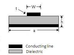 Fig.1 microstrip line
Microstrip line is used to carry Electro-Magnetic Waves (EM waves) or microwave frequency signals.
It consists of 3 layers, conducting strip, dielectric and Ground plane.
It is used to design and fabricate RF and microwave components such as directional coupler, power divider/combiner, filter, antenna, MMIC etc.
Microstrip line will have low to high radiation, will support 20 to 120 ohm impedance,supports Q factor of about 250. Difficult to mount chip in shunt mode but easy in series mode.
The RF/microwave product made using microstrip line is less expensive and lighter in weight compare to its waveguide counterpart. Usually FR-4 dielectric substrate is used as PCB for microstrip based etching due to its low cost.
Different types of discontinuities exist in RF/microwave layout design. These include bends, T-junction, cross-junction, step in width, coupling and open ends. Parasitic effect introduced by these discontinuities will be reduced by use of constant impedance tapers for example; curved bends are used in place of sharp bends. Sharp edges are changed to curved edges in RF layout. In certain cases radial stubs of different types (series and shunt) are employed.
Microstrip based layout design is carried out by various RF & Microwave simulation software's from various companies such as Agilent, Eagleware, Microwave office, applied computational sciences, CST, Ampsa Multimatch etc.
Types of microstrip line

Fig.2 stripline, this type of microstrip line low radiation, Q factor of about 400 and will support 35 to 250 ohm impedance range. This type is poor for chip mounting.
Example: Calculate width of the strip(W) provided following details of the stripline.
Impedance(Zo) is 50 Ohm, dielectric constant is 4.5 (ε) and PCB is 5mm thick(T).
W = 377 T / Zo sqrt(ε)
Width W is about 17.78 mm
 Fig.3 suspended stripline, this type of microstrip or transmission line
will have low radiation, Q factor of about 500 , impedance from 40 and 150 range. It is fair to mount chip on suspended stripline.
Fig.3 suspended stripline, this type of microstrip or transmission line
will have low radiation, Q factor of about 500 , impedance from 40 and 150 range. It is fair to mount chip on suspended stripline.

Fig.4 slotline,this type of microstrip line will have medium radiation, support Q factor of about 100, impedance from 60 to 200. It is easy to mount chip in shunt mode and difficult to mount in series mode.
 Fig.5 coplanar waveguide, this type of microstrip line will have medium radiation, support Q factor of 150, impedance from 20 to 250. It is easy to mount chip in both series and shunt mode.

Fig.6 finline, this type of microstrip line has no radiation and Q factor of 500. It is fair to mount chip using this type of transmission line.
RELATED LINKS
stripline basics and types
Microstrip line variants
Slotline basics and types
Finline basics
CPW(Coplanar Waveguide) basics
Types and basics of coaxial line
Types and basics of transmission line
RF Terms-Useful for RF design and testing.
RF-This page describes what is RF
Microstrip line impedance calculator
Microstrip line impedance calculator