Waveguide basics tutorial
This waveguide tutorial covers waveguide basics, waveguide types,waveguide propagation modes,waveguide impedance matching devices,waveguide dimensions and link to waveguide components manufacturer.
Electromagnetic waves are carried from one point to the other by many means such as coaxial cable, two wire line, optical fiber, microstrip lines, waveguide etc. The waveguide is the hollow metallic conductor carrying usually high frequency or microwave frequency. Operating range of waveguide is approx. from 300 MHz to 300 GHz. Waveguide behaves much like a High Pass Filter and is basically a passive microwave device. It will support waves above a certain cut off frequency. If the operating frequency lies below the waveguide cutoff frequency, propagation does not take place and wave is said as evanescent. Power loss occurs in the walls of waveguide due to induced current, in order to reduce this loss walls are designed with as much low resistance as possible.
Waveguide types
There are two main types of waveguide, rectangular and circular.

Rectangular waveguide: It looks as shown in fig.1.
Cutoff wavelength equation for rectangular waveguide is define below.
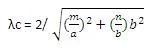
Here, m= number of half-wave along broad side dimension,
N= number of half-wave along the shorter side.
For dominant mode TE10, m=1, n=0 and hence, λc= 2(broad dimension) =2a
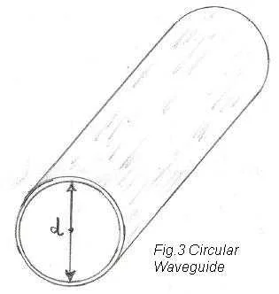
Circular waveguide: It looks as shown in fig.3.
Cutoff Frequency equation for circular waveguide fc is defined below ,
fc= (1.8412 * c /2*pi*a)
Where, c is the speed of light within waveguide and a is the radius of the circular cross section.
Fc=
For dominant mode TE11, λc= 1.71(diameter)=1.71d
Waveguide Propagation modes
Various TE and TM modes are supported in waveguide. As it supports waves above a particular cutoff frequency, mode with lowest cutoff frequency is called dominant mode.
TE mode stands for transverse electric mode, here electric field (E field) is perpendicular to the direction of propagation and magnetic field (H field) is in the direction of the propagation.
TM mode stands for transverse magnetic mode, here magnetic field is perpendicular to the direction of propagation and electric field is in the direction of the propagation.
Dominant mode is TE10 for rectangular waveguide and TE11 for circular waveguide
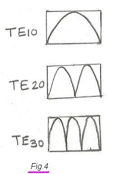
Fig.4 depicts TE10,TE20 and TE30, In TE10, the number 1 indicates half-wave electric field exists along X- direction.
In TE20, the number 2 indicates two half-wave electric fields exist in X-direction.
Waveguide Impedance matching devices
There are various impedance matching devices used for waveguide tuning.
They are various metallic objects such as Iris, posts or screws, E-H tuner,
probe, double stub tuner etc. These metal pieces are introduced into the waveguide near
the source or reflected waves in order to eliminate standing waves.
Iris
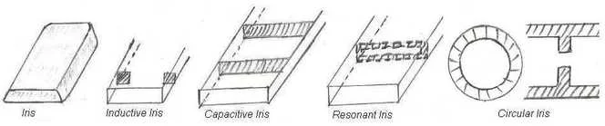
Iris is used to introduce inductance (L), capacitance (C) or combination of both L and C into a
rectangular waveguide. It is simply a metal plate as shown in fig.5.
Various types of iris such as inductive, capacitive, resonant are shown here based on how
they are inserted into a waveguide. Inductive Iris has advantage over the capacitive iris
in high power waveguides. Resonant window or iris produce combined effects of inductive and
capacitive windows.
Post/Screw
It acts as a shunt capacitive reactance in the waveguide if it is partially inserted. If fully inserted with connection to waveguide wall on both the sides then it introduces inductive reactance.
E-H Tuner They are basically used for waveguide tuning with the help of hybrid tees. Using E-H tuner both E and H arm reactance can be adjusted continuously. They remove any undesired reflections in a waveguide.
Similarly waveguide to coaxial probe and double stub tuner are used for waveguide impedance matching.
Waveguide disadvantages/demerits
- waveguide is not suitable to operate at low frequencies due to increase of its dimensions.
- Operate at narrower bandwidth
- It is very bulky, not flexible, not economical
- Propagation of EM waves takes place due to reflection in the waveguide hence TEM mode is not possible.
Waveguide dimensions
WR-62 means large dimension is 0.62 inch and shorter dimension is 0.62/2 inch. Refer Waveguide table in General section,which mentions various waveguide designations with their sizes and cutoff frequencies. Follow link below.
Useful Waveguide Links
Waveguide components manufacturer
waveguide dimensions table
Rectangular waveguide vs Circular waveguide
Waveguide tee
Waveguide attenuator
Waveguide isolator
Waveguide transition
Waveguide Adapter
Waveguide Switch
Waveguide filter
Waveguide calculators
Circular Waveguide Cutoff frequency
Rectangular waveguide cutoff frequency
waveguide breakdown power