GPRS Tutorial
GPRS is the short form of General Packet Radio Service. It is used in tandem with GSM network and mainly used for data connections through packet switched network. It is mainly used to browse/access internet in mobile devices. GPRS is GSM based packet switched technology. It requires MS (mobile subscriber) or user to support GPRS, network operator to support GPRS and services for the user to be enabled to use GPRS features. In GSM, Mobile subscriber is allocated one time slotwhile in GPRS it is possible to have a multislot allocated to users. Two major changes have been incorporated in GSM network to provide GPRS functionality. One is Channel coding unit is upgraded at BTS and the other is Packet Control Unit added suitably at BSC or between BSC-MSC, as mentioned below.
Network Architecture of GPRS in wireless communication
It is a packet switched wireless data communication technology. GPRS enables mobile devices to access the internet and other data services over a cellular mobile network. The main elements of a GPRS architecture are Mobile Station (MS), Base Station Subsystem (BSS), Serving GPRS Support Node (SGSN), Gateway GPRS Support Node (GGSN), Home Location Register (HLR), Authentication Center (AuC), Operation and Maintenance Center (OMC), Charging Gateway (CG) and so on.
Entire GPRS network can be divided for understanding into following basic elements.
Packet Control Unit (PCU) : This PCU is the core unit to segregate between GSM and GPRS traffic.
It separates the circuit switched and packet switched traffic from the user
and sends them to the GSM and GPRS networks respectively which is shown in the figure above. In GPRS PCU has following two paths.
1. PCU-MSC-GMSC-PSTN
2. PCU-SGSN-GGSN-Internet (packet data network)
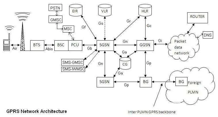
Serving GPRS Support Node(SGSN) : It is similar to MSC of GSM network. SGSN functions are outlined below.
• Data compression which helps minimise the size of transmitted data units.
• Authentication of GPRS subscribers.
• Routing of data to the corresponding GGSN when a connection to an external network is needed.
• Mobility management as the subscriber moves from one PLMN area to the another PLMN, and possibly one SGSN to another SGSN.
• Traffic statistics collections.
Gateway GPRS Support Node(GGSN) : GGSN is the gateway to external networks such as PDN (packet data network) or IP network. It does two main functions. It is similar to GMSC of GSM network
• Routes mobile destined packet coming from external IP networks to the relevant SGSN within the GPRS network
• Routes packets originated from a user to the respective external IP network
Border Gateway (BG) : It is a kind of router which interfaces different operators GPRS networks. The connection between two border gateways is called GPRS tunnel. It is more secure to transfer data between two operators using their own PLMN networks through a direct connection rather than via the public Internet which is less secure. For this both operators need to agree to provide such connectivity and terms and conditions including charging terms.
Charging Gateway (CG) : GPRS users have to be charged for the use of the network, this is taken care by Charging gateway. Charging is done based on Quality of Service or plan user has opted either prepaid or post paid. This charging data generated by all the SGSNs and GGSNs in the network is referred to as Charging Data Records (CDRs). The Charging Gateway (CG) collects all of these CDRs, processes the same and passes it on to the Billing System.
DNS server : Connected at ISP location or at IP network. It converts domain name to IP addresses required to establish internet connection and to deliver web pages on user's terminal screen.
Intra PLMN : An IP based network inter-connecting all the above mentioned GPRS network elements in one PLMN area.
Inter PLMN : Connection between two different PLMN areas.
GPRS Frame Structure
GPRS uses FDMA to divide 25 MHz to 124 channels and each channel is further divided using TDMA into 8 time slots similar to GSM. Each of the frequency and time slot make one physical channel. We have seen that in GSM 26 Frame Multiframe (MF) and 51 Frame MF is used for traffic/SACCH and Signaling channels respectively. Logical channels are time multiplexed on physical channels.In GPRS 52 Frame MF structure is used for traffic as well as signalling. Each time slot follow 52 frame MF structure. Resource allocation here is called radio block or RLC block. 4 consecutive bursts in 4 consecutive TDMA frames in the same time slot is called radio block. In GPRS frame structure of 52 frame MF consists of 12 radio blocks for user data, 2 PTCCH frames for the Timing advance calculation and 2 idle frames used for neighbour cell measurements. Only for few of the initial network entry logical frames such as FCCH,SCH and BCCH 51 Frame MF structure of GSM is used in GPRS. Figure 2. depicts GPRS 52 frame Multiframe structure. PTCCH frames are marked by T and Idle frames by X. As shown it requires four consecutive time slots(carrying bursts) in four consecutive TDMA frames to fill 456 data bits. each burst carry 114 bits.
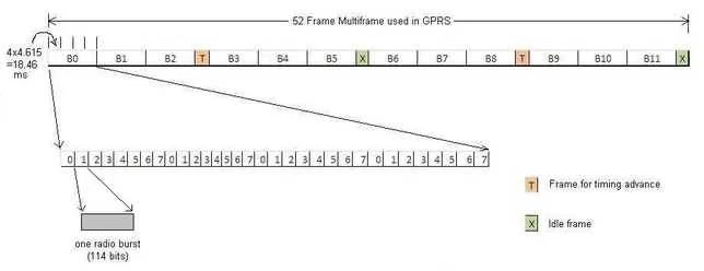
Different logical frames goes in these 12 blocks both in the downlink and uplink
to carry signalling as well as traffic data.
1 TDMA Frame = 8 TNs(Time Slot Nos)(4.615 ms)
One 52 Frame MF = 4.615 (52) = 240 ms
One super frame = 25.5 (52 Frame MF) = 240 x 25.5 = 6.12 sec
One hyperframe = 2048 (6.12 sec) = 3 h 28 min 53 sec 760 ms
Remember that UEs to BSS link is called uplink and BSS to UEs link is called downlink.Unlike GSM where time slot is dedicated to UE/MS, in GPRS one time slot is used by multiple UEs at different time. UEs are multiplexed using unique USF (Uplink Status Flag) on same time slot. USF helps differentiate UEs on BSS side. On downlink UEs are multiplexed using TFI (Temporary Flow Identity) which differentiate concurrent TBFs (Temporary Block Flows).
Mapping of coding schemes based on stealing flags
Stealing flags are used to dictate receiver about which coding scheme is used at transmitter end.
There are 8 stealing flags to signify 4 coding schemes as mentioned below in the table, instead of 2 possible stealing flags.
| Coding Scheme | Stealing Flag |
| CS-1 Scheme | 11111111 |
| CS-2 Scheme | 11001000 |
| CS-3 Scheme | 00100001 |
| CS-4 Scheme | 00010110 |
GPRS IP addressing
Same IP version 4 (IPv4) and IP version 6 (IPv6) is used with GPRS as used for other internet services/protocols.
GPRS Handset classes
Class A- This type of handsets houses two transceivers. Hence can send and receive data and voice at the same time.
Both voice and data call can work at the same time.
Class B- This type of handsets can send/receive data or voice, but not both at the same time.
Class C- This type allows only one means of connectivity wither voice or data. For example, GPRS card available to be inserted in laptop/desktop will only provide GPRS data connectivity.
GPRS Coding Schemes
As per GPRS standards, there are four possible air interface coding schemes viz. CS1,CS2,CS3 and CS4. Each has different error correction capability and throughput specifications.
CS1 has throughput <= 8kbps
CS2 has throughput <= 12kbps
CS3 has throughput <= 14.4kbps
CS4 has throughput <= 20kbps
GPRS Channels
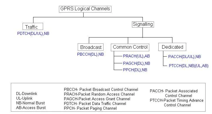
Let us go through GPRS logical channels.
Logical channels are named and used in GPRS network are PBCCH, PPCH, PAGCH,PNCH,PRACH, PACCH,PTCCH,PDTCH.
These channels are divided as mentioned below based on their functions.
Broadcast channel- Packet Broadcast Central Channel (PBCCH)
Common control channels- Packet Paging Channel (PPCH),Packet Access Grant Channel (PAGCH),Packet Notification Channel (PNCH),Packet Random Access Channel (PRACH)
Dedicated control channels-Packet Associated Control Channel (PACCH),Packet Timing Advance Common Control Channel (PTCCH)
Dedicated traffic channel-Packet Data Traffic Channel (PDTCH)
GPRS Logical Channel functions are described below.
PDTCH- Used for data traffic, bidirection between MS(Mobile Subscriber) and BSS(base station subsystem)
PBCCH- Used for Broadcast signalling control, from BSS to MSs
PRACH- Used for random access, from MSs to BSS
PAGCH- Used for Access Grant indication, from BSS to MSs
PPCH-Used for Paging, from BSS to MSs
PNCH- USed for notification purpose, from BSS to MSs
PACCH- Used for Associated control, bidirectional
PTCCH- Used for timing advance control, bidirectional
GPRS QoS
Based on different GPRS applications there are different GPRS QoS services. Applications can be real-time multimedia,Web browsing and e-mail. GPRS defines various QoS profiles based on parameters viz. service precedence or priority,reliability,delay and throughput.
GPRS Channel Allocation
In the Uplink, MS sends channel request to the network(BSS) on PRACH/RACH. Network responds on PAGCH/AGCH to MS,mentioning which PDCH MS can use for data transfer. Network dictates which time slots MS(UE) can using a field called USF. USF is carried in MAC header in the downlink control/data block. USF is 3 bit field.
In the downlink, network(BSS) sends paging request message to the MS on PPCH/PCH. MS sends packet channel request on PRACH/RACH to network,network replies as mentioned above on PAGCH/AGCH. MS sends paging response to network on PACCH.
GPRS MAC Modes
Let us examine mac modes of GPRS network. There are two different types of phases(phase-1 and phase-2) by which TBF establishment takes place in GPRS. TBF(Temporary Block Flow) is composed of no. of RLC/MAC blocks(of one or more LLC frames). Each TBF is assigned with one unique TFI(Temporary Flow Identity) in both directions(uplink and downlink). Hence it is possible to allocate same time slot for more than one GPRS user. The most common GPRS classes supported in both network and MS(UE) are class 10,12 and 33.
TBF is temporary and maintained till data transfer is completed.
It is a connection between two RR entities at L3 level.
In 1-phase access,network knows which allocation is for which MS,
when it received first TBF.
In 2-phase access, network identies which resource allocation is for which MS.
This is because,MS sends packet resource request after receiving channel assignment from network.
Network responds with packet uplink assignment.
Dynamic Allocation(DA):
In DA, MS will decode all the USF values on the
downlink PDCHs associated with uplink PDCHs.
Extended Dynamic Allocation:
Here MS will not monitor all the USFs. Once MS decodes one USF value,
it will transmit on multiple time slots in the uplink
from the slot corresponding to the downlink side.
Bit maps are transmitted during assignment message, which indicates which time slots are needed in downlink and uplink for transmission. 1 in the bitmap indicates transmission and 0 indicates no transmission. There is a field called Granularity which indicates whether transmission should happen on consecutive 4 bursts or on 1 burst.
Fixed Allocation:
In Fixed allocation, each MS is assigned with fixed allocation in the uplink to be used for
transmission of radio blocks on PDCHs. This is also done using bitmaps
communicated by network to the MSs.
GPRS standard References
For GPRS refer 3GPP 44.06 standard.ETSI GPRS standard documents are available from following link.
https://www.etsi.org/website/technologies/gprs.aspx
Conclusion : In this GPRS tutorial, we have learnt how GPRS network architecture, its innovative frame structure, channel types, MAC modes and security mechanisms have paved the way for more advanced technologies in mobile wireless communication.
Similar posts on GPRS network
Test Mode A vs Test Mode B
GPRS RxQUAL vs BER
EGPRS Basics
EGPRS vs GPRS
What is GPRS
GPRS protocol stack
GPRS Modem vendors
GSM versus GPRS
EDGE/EGPRS Basics
What is GPRS
GPRS/EGPRS Modulation-Coding Schemes