RF Power Amplifier Design basics | RF Power Amplifier
This page describes RF power amplifier design basics including RF amplifier stages, power amplifier classes, specifications, applications and manufacturers. The solid state rf power amplifier design example is also mentioned.
RF Amplifier definition
Amplifier is the device or module which boost (i.e. increases power) the signal of certain radio frequency. Mainly it is referred as RF power amplifier owing to its use to amplify radio frequency signal or increase power at the input to give more power at the output.
RF Power Amplifier Stages
Following are the RF power amplifier stages or modules.
1.Input Matching network: Used to match the amplifier device with input 50 Ohm impedance line.
2.Amplifiers one or in stages: Based on the requirement of the gain in the circuit one or more amplifier devices are used. If multiple devices are used they are connected either in parallel or in cascade based on P1dB requirement.
3.Biasing network: Used to provide bias/voltage to the device.
4.Accessories network: They are basically different methods and facilities to improve stability and linearity characteristics of the amplifier.
5.Output Matching network: Used to match the amplifier device with output 50 Ohm impedance line.
RF Power Amplifier Classes
Following are the rf power amplifier classes in which amplifier normally operates.
In order to operate a transistor for a certain class, the gate and drain dc voltages have to be biased carefully to the certain operating point (quiescent point or q-point)
1.Class A- q point is about 0.5, it is biased at close to half of its saturated current. Conduction angle is 2pi i.e. 360 degree.
2.Class B- q point is 0, it is biased at a point where it draws nearly zero DC current. Conduction angle is pi.
3.Class AB- q point is between 0 and 0.5. Conduction angle is between pi and 2pi.
4.Class C- q point is below 0. Conduction angle is between 0 and pi.
RF Power Amplifier Technical Specifications
Following are typical rf power amplifier specifications one has to consider before purchase.
Frequency Range- 5925 to 6425 MHz
1dB Gain Compression point- 5 Watt
Power Gain- 40dB
Ripple/Response over the frequency band- 2dB
Input and Output VSWR- 1.25:1 (19dB return loss)
Example Solid State RF Power Amplifier Design
Following figure mentions devices used in 5 Watt Low cost Feed Mount Solid State Power Amplifier ( SSPA ) for C band application.
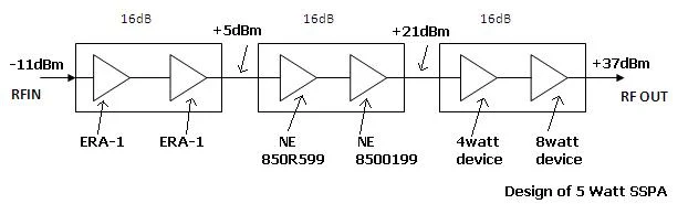
There are three stages in the design of SSPA as shown viz. input, output and intermediate. The figure depicts discrete amplifier MMICs used in the design. The power supply section should be designed to convert -48 V DC to appropriate device voltages. The appropriate heatsink should be designed in order to dissipate heat.
RF amplifier applications
RF amplifier can be used for various functions in the communication chain. For providing gain to the signal before transmission it is called as power amplifier and will be connected to the transmitting antenna. When it is connected just after reception of the signal it is called as Low Noise Amplifier (LNA). LNA amplifies received distorted signal without much amplifying noise. It is used as variable Gain Amplifier in the highly changing mobile channel; hence help recover the transmitted information in the receiver.
RF Power Amplifier Manufactures
• Anadigics
• Agile Microwave Technology Inc
• Analog devices
• empower rf
• Skyworksinc
For website details of RF Power amplifier manufacturers, Read more.
RELATED LINKS
RF Terminology
Satellite Terminology
VSAT system overview
FDMA versus TDMA versus CDMA
VSAT SCPC
VSAT MCPC
RF Transceiver basics
C band RF Transceiver Design and Development
Microstrip basics and types
Design of RF frequency converter
RF Power Amplifier
what is modulation
satellite Modem design
RF Link Budget