40 Gigabit Ethernet Physical Layer | 40g Ethernet PHY
This 40 Gigabit ethernet should support following features:
• Support full-duplex operation only
• Preserve the 802.3 / Ethernet frame format utilizing the 802.3 MAC
• Preserve minimum and maximum frame size of current 802.3 standard
• Support a bit error rate (BER) >= 10-12
• Provide appropriate support for optical transport network
• Support a MAC data rate of 40 Gbps
-Provide physical layer specifications which support 40 Gbps operation over:
-at least 10km on SMF (single mode fibre)
-at least 100m on OM3 MMF (multi-mode fibre)
-at least 7m over a copper cable assembly
-at least 1m over a backplane
The MAC layer corresponds to Layer 2 of the OSI model. This is interfaced with Ethernet PHY layer. This physical layer will be interfaced with fiber or copper. The ethernet physical layer corresponds to layer-1 of the OSI stack.
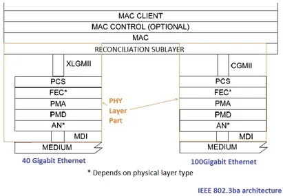
The figure-1 depicts sublayers of 40gbps Ethernet PHY. As shown in the figure, 40g PHY layer composed of sublayers which include Reconciliation sublayer, XLGMII, PCS, FEC(forward error correction), PMA, PMD, AN(auto-negotiation) and MDI.
40gbps Ethernet | RS XLGMII PCS PMA PMD MDI
Reconciliation sublayer (RS):
RS adapts the bit serial protocols of the MAC to the parallel format of the PCS service interface.
The RS converts between the MAC serial data stream and the parallel data paths of the
XLGMII/CGMII.
The RS maps the signal set provided at the XLGMII to the PLS service primitives provided
at the MAC.
The RS sublayer generates continuous data or control characters on the transmit path and expects continuous
data or control characters on the receive path.
The RS sublayer participates in link fault detection and reporting by monitoring the receive path for status
reports that indicate an unreliable link, and generating status reports on the transmit path to report
detected link faults to the DTE on the remote end of the connecting link.
XLGMII:
It is the optional logical interfaces between the MAC sublayer and the Ethernet Physical
Layer. This sublayer has following features.
• This sublayer XLGMII supports a speed of 40 Gigabit per Second.
• Data and delimiters are synchronous to a clock reference.
• It provides independent 64-bit wide transmit and receive data paths.
• It supports full duplex operation only.
Each direction of data transfer is independent and serviced by data, control, and clock signals.

40GBASE-R Physical Coding Sublayer (PCS):
In order to meet 40 Gbps data flow, IEEE community have developed multilane distribution system for
data through the PCS sublayer of the ethernet physical layer interface.
Figure-2 depicts PCS for 10 Gbps ethernet which delivers single PCS lane of data.
For 40 Gbps, first ethernet frame is broken into 66 bit words, and these words are transmitted simultaneously across all the four lanes. Signalling on each lane operates at the rate of 10.3125 Gbaud. The same have been depicted in the figure-4 below.

Figure-3 depicts 40 Gigabit PCS sublayer transmitter and receiver modules used for data processing. The transmit PCS, therefore, performs the initial 64B/66B encoding and scrambling on the aggregate channel (at 40 gigabits per second) before distributing 66-bit block in a round robin basis across the multiple lanes.
Here blocks consist of 66 bits. The first two bits of a block are the synchronization header. Blocks are either data blocks or control blocks. The sync header is 01 for data blocks and 10 for control blocks. Hence there will be always a transition between the first two bits of a block. The remainder of the block contains the payload. The payload is scrambled and the sync header bypasses the scrambler.
Data blocks contain eight data characters. Control blocks begin with an 8-bit block type field that indicates the format of the remainder of the block.

For 40 Gigabit Ethernet 4 PCS lanes support interface widths of 1, 2 and 4 channels/wavelengths. Once the PCS lanes are created they can be multiplexed into any of the supportable interface widths.
In order to support deskew and reordering of individual PCS lanes at the receive PCS, alignment markers are added periodically to each PCS lane. The alignment markers shall be inserted after every 16383 66-bit blocks on each PCS lane. All multiplexing is done at the bit-level.

Alignment marker carry specific contents for 40 Gigabit as well as 100 Gigabit ethernet. The same have been mentioned in the IEEE standard 802.3, section six. Refer table 82-3 for 40GBASE-R alignment marker encoding.
As mentioned the round-robin bit-level multiplexing can result in multiple PCS lanes being multiplexed into the same physical channel. The unique property of the PCS lanes is that no matter how they are multiplexed together, all bits from the same PCS lane follow the same physical path, regardless of the width of the physical interface. This enables the receiver to be able to correctly re-assemble the aggregate channel by first de-multiplexing the bits to re-assemble the PCS lane and then re-align the PCS lanes to compensate for any skew.
FEC and AN(auto-negotiation) sublayers depends on physical layer medium.
FEC(Forward Error Correction) sublayer:
FEC sublayer lies between the PCS sublayer and PMA sublayer. It may also exist between
two PMA sublayers.
It is instantiated for each PCS lane separately.
The FEC sublayer is specified in Clause 74 of the IEEE ethernet standard.
PMA(Physical Medium Attachment) sublayer:
This sublayer provides medium independent means for PCS sublayer to
support the use of range of different physical mediums.
40GBASE-R PMA sublayer performs the mapping of transmit and receive data
streams between the PCS and PMA via the PMA service interface.
It also does mapping and multiplexing of transmit and receive data streams between
the PMA and PMD via the PMD service interface.
The PMAs also perform re-timing of the received data stream when appropriate. It provides data loopback at the PMA or PMD service interface as well as test pattern generation and checking optionally. Refer Clause 83 of ethernet standard for more details on 40GBASE-R PMA sublayer.
PMD(Physical Medium Dependent) sublayer:
The Physical Medium Dependent(PMD) sublayer is responsible for interfacing to the transmission medium. The
PMD is located just above the MDI (Medium Dependent Interface).
Auto Negotiation(AN sublayer):
This sublayer provides a linked device with the capability to detect the abilities (modes of operation)
supported by the device at the other end of the link, determine common abilities and configure for joint
operation.
The auto-negotiation support/status field shall contain a bitmap that identifies the auto-negotiation support
and current status of the local IEEE 802.3 LAN station.
It is used in 40 Gbps backplane physical layer and 40 Gbps copper physical layer.